Wiring Question

General forum on troubleshooting electrical problems and modifications to electrical systems

Moderator: rztom

Post Reply
Message
Author
User avatar
Smoker
Posts: 4783
Joined: Sun Mar 23, 2008 8:08 pm

Wiring Question

#1 Post by Smoker » Mon May 03, 2021 3:54 pm

I'm using an '07 GSXR 600 front end on my RZ, so I'd like to use the '07 GSXR 600 ignition key switch.

I have 2 questions about the GSXR switch wiring. Ignition is brand new. Hope someone can help.

Ignition wires look like this:

Image

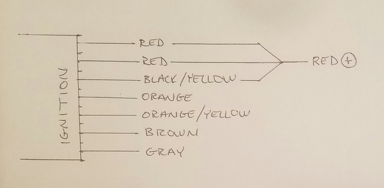
The RED, RED, BLACK/YELLOW, and ORANGE are larger wires. (approx.18g)
The ORANGE/YELLOW, BROWN, and GRAY are smaller wires. (approx. 22g)

RED, RED, and BLACK/YELLOW = Always Hot
ORANGE, and ORANGE/YELLOW = Hot with ignition "On"
BROWN = Hot with ignition "PKG LAMP"
GRAY = Never Hot

#1- Test light lights up slowly, and is dim with ORANGE/YELLOW wire. Why?

#2- Test light never lights up with GRAY wire. Why?

Thanks. :smt006

User avatar
Smoker
Posts: 4783
Joined: Sun Mar 23, 2008 8:08 pm

Re: Wiring Question

#2 Post by Smoker » Tue May 04, 2021 12:07 am

Wasted a lot of time and can't find the correct schematic.

I figured out that the GRAY wire probably goes to the dash for speedo/tach lighting, and the ORANGE/YELLOW wire probably goes to the (GSXR) ECU.

I think the correct conclusion is that the switch isn't working properly.

I may not need those 2 wires, anyway. [smilie=dunno.gif]

MK
Posts: 818
Joined: Sat Nov 26, 2005 11:44 am
Location: Wolfenbüttel, Germany
Contact:

Re: Wiring Question

#3 Post by MK » Tue May 04, 2021 5:23 am

You need the switch scheme or you need to measure it on your own.
(Which wire is connected/disconnected to/from which when the key is in on/off/park/lock positions)

Looks like this one (Main switch on the lower left corner)
https://www.powerdynamo.biz/deu/systems ... re_mod.jpg

On the 350 YPVS, the important part is to
- connect black and black/white when being in "off"
- connect red and brown when being in "on"
- disonnect red and brown when being in "off"

(All colors on the RD harness)
Bye
Martin

User avatar
Smoker
Posts: 4783
Joined: Sun Mar 23, 2008 8:08 pm

Re: Wiring Question

#4 Post by Smoker » Tue May 04, 2021 8:31 pm

Messages from the peanut gallery-

"some Kawasaki ignitions have a strategically placed resistor so that the bike can’t be hot wired"

Most of the similar schematics I found show the ORANGE/YELLOW (dim) wire going to the ECU. One of the schematics I found said (theft) next to that wire.

"there will def need to be a ground in there"

All the similar schematics I found show a BLACK/WHITE wire that goes to ground.

Image

Image

The info I found said ignition switches don't need to be grounded.

To confound this issue, check out the wiring on my switch. This isn't modified. Brand new from Suzuki. The BLACK/YELLOW wire is spliced into the 2 RED wires.

Image

Image

User avatar
Smoker
Posts: 4783
Joined: Sun Mar 23, 2008 8:08 pm

Re: Wiring Question

#5 Post by Smoker » Tue May 04, 2021 8:44 pm

MK wrote: Tue May 04, 2021 5:23 am You need the switch scheme or you need to measure it on your own.
I've searched and can't find the switch scheme.
I've been trying to figure it out with a test light.
I think I have a multimeter somewhere.

MK
Posts: 818
Joined: Sat Nov 26, 2005 11:44 am
Location: Wolfenbüttel, Germany
Contact:

Re: Wiring Question

#6 Post by MK » Wed May 05, 2021 4:29 am

If the switch half way matches the color diagram, it's not suitable for a stock RD CDI.
The reason is that you need a contact pair that gets connected on "off" and disconnected on "on" for the kill switch wire (that's the black/white on the stock CDI)
If you leave that unconnected, everybody could start the engine in "off" position.

The above scheme only offers contacts that get connected on "on" or "p".
This would work with an aftermarket DC CDI like the Ignitech. If you connect 12V supply by switching to "on", it'll work, if you disconnect the 12V supply by "off" it'll stop and can't be started.
Bye
Martin

User avatar
Smoker
Posts: 4783
Joined: Sun Mar 23, 2008 8:08 pm

Re: Wiring Question

#7 Post by Smoker » Wed May 05, 2021 5:43 am

Thanks, Martin- but I don't know if my components will work, even after reading your explanation.

I'm not using a stock RD CDI. I'm using the Zeel CDI-RZ1 which has a GRAY wire that goes to the BLACK/WHITE kill switch wire.

I'm also using an M-Unit which has an input for a KILL wire.

The aftermarket KILL switch I have is normally open. The circuit is completed when the momentary button is pushed. I'm hoping it will work with either the Zeel CDI or the M-Unit.

I'll have to wait until the engine is done, but testing should be easy. If I switch the bike ON and kick it over, I should see spark at the plugs if the KILL switch is okay. Push the KILL switch and kick it over should have no spark.

MK
Posts: 818
Joined: Sat Nov 26, 2005 11:44 am
Location: Wolfenbüttel, Germany
Contact:

Re: Wiring Question

#8 Post by MK » Wed May 05, 2021 7:20 am

The CDI RZ-1 is a "replacement" for the stock CDI but without a curve - it sparks at a constant timing that needs to be adjusted by turning the base-plate.
It does not operate on 12V but on the bikes source coils, so it shows the same effect than the stock CDI. If kill wire is not grounded, it'll start despite ignition switch being set to "off".
Bye
Martin

User avatar
Smoker
Posts: 4783
Joined: Sun Mar 23, 2008 8:08 pm

Re: Wiring Question

#9 Post by Smoker » Wed May 05, 2021 4:57 pm

MK wrote: Wed May 05, 2021 7:20 am The CDI RZ-1 is a "replacement" for the stock CDI but without a curve - it sparks at a constant timing that needs to be adjusted by turning the base-plate.
It does not operate on 12V but on the bikes source coils, so it shows the same effect than the stock CDI. If kill wire is not grounded, it'll start despite ignition switch being set to "off".
I'm using the Zeeltronic VCDI-04 with the CDI-RZ1, so the ignition is programmable.

The GREY wire on the CDI-RZ1 goes to the B/W wire on the OEM KILL switch. So, the GREY wire is grounded with the engine running.

Image

Suppose I connect the GREY wire directly to ground. Engine should run, but the KILL switch would not be connected.

VCDI RED wire is connected to switched power ("ON") using the GSXR ignition switch. So, when the key is "OFF", the bike can't start.

Hoping I can connect my aftermarket KILL switch (normally open/not grounded) to the M-Unit KILL input, and connect the VCDI RED wire to the IGNITION output on the M-Unit.

Image

If all else fails, I should be able to use a relay to fix the issue. Right?

Image

MK
Posts: 818
Joined: Sat Nov 26, 2005 11:44 am
Location: Wolfenbüttel, Germany
Contact:

Re: Wiring Question

#10 Post by MK » Thu May 06, 2021 3:27 am

If you have a VCDI in between, it likely will stop sparking when 12V supply is switched off.

But for the Grey cable on the CDI RZ-1 you're on the wrong path. The spark is "killed" when it's grounded and engine will run, if it's not grounded.
Bye
Martin

Post Reply