elettric diagram RZV500R
Moderator: rztom
elettric diagram RZV500R
Someone have elettric diagram of RZV500R 1GG?
-
bokusouchi
- Posts: 80
- Joined: Sat Apr 13, 2013 4:36 am
Re: electric diagram RZV500R
here it is :
https://i.postimg.cc/sxzqMcCz/electric-rzv500r.png
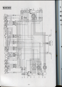
This is from the RZV500R worshop manual (published in 1984 ) so it is 51X but i believe that the diagram is same for 1GG .
If you have difficulties with japanese , use https://translate.yandex.com/
https://i.postimg.cc/sxzqMcCz/electric-rzv500r.png
This is from the RZV500R worshop manual (published in 1984 ) so it is 51X but i believe that the diagram is same for 1GG .
If you have difficulties with japanese , use https://translate.yandex.com/
Re: elettric diagram RZV500R
Thank you very much! But I'm problem with Japanese... 
Are you able to sign what is the wire for switch bottom for temperature/fuel display? where wire goes to....
Thanks

Are you able to sign what is the wire for switch bottom for temperature/fuel display?
 where wire goes to....
Thanks
-
bokusouchi
- Posts: 80
- Joined: Sat Apr 13, 2013 4:36 am
Re: elettric diagram RZV500R
look for top left corner of diagram the switch is there . (it is marked "FREE/PUSH" )
As i said , you can use https://translate.yandex.com/ for translating the japanese .
The web site can recognize japanese in image and translate to english .
the image has to be < 5mb . so use gimp or another image editing sofware to cut a small corner of what you are interested in .
also turn the image you summit the proper way for Yandex to OCR the japanese .
(in case English is not you native langage , Yandex can also translate to other languages )
-
Bengt Weil
- Posts: 224
- Joined: Sat Aug 04, 2012 2:01 am
- Location: Ventura, California
Re: elettric diagram RZV500R
Temp Sensor = GRN/RD wire, which goes to the Function Switch.
Fuel Level Sensor = GRN and BLK wires - GRN wire goes to the Function Switch & BLK wire is ground
Temp/Fuel gauge has 3 wires - BLK is ground, BRN is 12V+ and GRN/RD goes to the Function Switch
Appears to me that the gauge is powered by 12V+ and the Function Switch by default allows the resistance to ground of the Temp Sensor to display on the gauge. Upon pressing the Function switch, it allows the resistance to ground of the Fuel Level Sensor to override the resistance of the Temp Sensor, changing the gauge reading accordingly.
Once you locate the 4 elements (Gauge, Temp Sensor, Fuel Level Sensor & Function Switch), just follow the wires. Hope this helps and good luck!
-
Paul Waterloo
- Posts: 32
- Joined: Mon Jun 15, 2020 11:44 am
- Location: Chicago, IL USA
Re: elettric diagram RZV500R
Here are the diagrams out of my manual. If you click the three vertical buttons at the top right of the page, you can download the high resolution images. Hope this helps.
https://photos.app.goo.gl/xaAgtELzFj6yoNeB7
https://photos.app.goo.gl/xaAgtELzFj6yoNeB7
1986 RZ500S (Number 3 of 150)
1993 BMW K1100RT
2003 BMW K1200GT
1993 BMW K1100RT
2003 BMW K1200GT
-
bokusouchi
- Posts: 80
- Joined: Sat Apr 13, 2013 4:36 am
Re: elettric diagram RZV500R
As far as i know , this summarises the main differences in electric diagram between the 3 basic models :
RZV500R (Japan) 51X , 1GG
80 km/h warning light in tachometer
no turn signals cancelling unit
no reed switch in speedometer
fuel gauge , and fuel/temp switch on right handle bar .
RD500LC 47X 1GE (Europe mainly )
turn signals cancelling unit
reed switch in speedometer
RZ500 (52X , 53G) Canada
turn signals cancelling unit
reed switch in speedometer
Headlight permanently on ( no on/off switch)
no pilot light
side stand switch and side stand control unit
Re: elettric diagram RZV500R
thank you everybody!!!!
My problem now is to find fuel sensor because in my RZV500R the general cable have used for restoring bike is for RD/RZ500 and the wire for fuel sensor is missing.....
Where i must search the fuel sensor in the bike?
Thanks
My problem now is to find fuel sensor because in my RZV500R the general cable have used for restoring bike is for RD/RZ500 and the wire for fuel sensor is missing.....
Where i must search the fuel sensor in the bike?
Thanks

Re: elettric diagram RZV500R
The sensor fit in the bottom of the tank, On the RZ/RD500 tank the fuel sender is blanked off, its the square just up from the fuel tap, I had a heck of a time finding one for mine, I got one is Japan eventually with a proper RZV tank,
Take a look at the pics here of the tank and you will see where the fuel sender fits.
Fuel Tank: https://www.jauce.com/auction/s796206382
Fuel sender https://www.jauce.com/auction/w443115390
Take a look at the pics here of the tank and you will see where the fuel sender fits.
Fuel Tank: https://www.jauce.com/auction/s796206382
Fuel sender https://www.jauce.com/auction/w443115390
1985 RZv500
1984 RZ500 Hybrid
1986 RG500 Walter Wolf
1986 RG500 Skoal Bandit
1984 RZ350
1984 RZ350 Hybrid
1981 RD350LC
1981 RD350LC Hybrid
2009 CR500AF Supermoto 250X
2007 CR500AF 250X
1988 YSR50 (2)
1989 VFR750R RC30
1984 GPZ750 Turbo
1984 RZ500 Hybrid
1986 RG500 Walter Wolf
1986 RG500 Skoal Bandit
1984 RZ350
1984 RZ350 Hybrid
1981 RD350LC
1981 RD350LC Hybrid
2009 CR500AF Supermoto 250X
2007 CR500AF 250X
1988 YSR50 (2)
1989 VFR750R RC30
1984 GPZ750 Turbo
Re: elettric diagram RZV500R
Ops... my fueltank restored is for RD500 model.. 
In your opinion it is posssible modify my fueltank making a neccessary holes ( i see model of holes in my fueltank....)
In your opinion it is posssible modify my fueltank making a neccessary holes ( i see model of holes in my fueltank....)
Re: elettric diagram RZV500R
Could be done I suppose, The only thing is the RZV has a metal plate inside the tank to stop the tank flexing when the sensor is tightened up, I thought about doing mine but ended up buying a tank instead..
1985 RZv500
1984 RZ500 Hybrid
1986 RG500 Walter Wolf
1986 RG500 Skoal Bandit
1984 RZ350
1984 RZ350 Hybrid
1981 RD350LC
1981 RD350LC Hybrid
2009 CR500AF Supermoto 250X
2007 CR500AF 250X
1988 YSR50 (2)
1989 VFR750R RC30
1984 GPZ750 Turbo
1984 RZ500 Hybrid
1986 RG500 Walter Wolf
1986 RG500 Skoal Bandit
1984 RZ350
1984 RZ350 Hybrid
1981 RD350LC
1981 RD350LC Hybrid
2009 CR500AF Supermoto 250X
2007 CR500AF 250X
1988 YSR50 (2)
1989 VFR750R RC30
1984 GPZ750 Turbo